3.5 Introduction of ArduinoBlocks.com and Wemos D1 board
Learning Objectives:
After this lesson, students can
- use ArduinoBlocks.com to program a Wemos D1 board;
- use a multimeter to measure DC voltages.
1. INTRODUCTION OF ARDUINOBLOCKS.COM
IMPORTANT NOTE:
The Arduinoblocks connector must be run at the background for program uploading.
Since ArduinoBlocks connector version 5 supports the use of serial port in Wemos D1 board but version 4 cannot, we will use Arduinoblocks connector version 5.
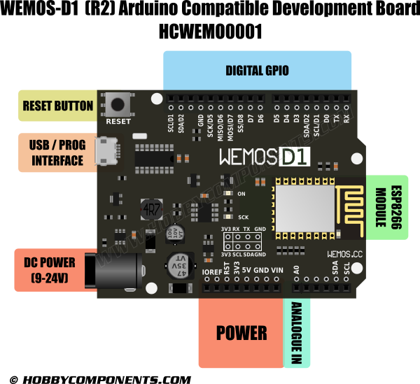
2. INTRODUCTION OF WEMOS D1
Features of Wemos D1 R2 Wifi -Esp8266 Development Board:
- The D1 R2 is a mini wifi board based on ESP-8266EX
- 11 digital input/output pins, all pins have interrupt/PWM/I2C/one-wire supported (except D0)
- 1 analog input (3.3V max input)
- A Micro USB connection
- Compatible with Arduino
- Compatible with nodemcu
- Several shields, sensors and output devices that are manufactured for the Arduino platform will work on the WeMos-D1R2.
- Builtin WiFi
Technical specifications (Wemos D1 R2):
Microcontroller ESP-8266EX Operating Voltage 3.3V Digital I/O Pins 11 (All IO is work at 3.3V) Analog Input Pins 1, max 3.3V input Clock Speed 80MHz/160MHz Flash 4M bytes Length 68.6mm Width 53.4mm Weight 25g
On-Board Switching Power Supply:
- Input Voltage Range: 7V to 12V ? (varying from different manufacturers)
- Output: 5V at 1A Max ?
WeMos D1 R2 Pinout

WeMos D1 Mini Pinout

Pin Function ESP-8266 Pin TX TXD TXD RX RXD RXD A0 Analog input, max 3.3V input A0 D0 IO GPIO16 D1 IO, SCL GPIO5 D2 IO, SDA GPIO4 D3 IO, 10k Pull-up GPIO0 D4 IO, 10k Pull-up, BUILTIN_LED GPIO2 D5 IO, SCK GPIO14 D6 IO, MISO GPIO12 D7 IO, MOSI GPIO13 D8 IO, 10k Pull-down, SS GPIO15 G Ground GND 5V 5V – 3V3 3.3V 3.3V RST Reset RST
[!] Except D0, All of the IO pins have interrupt/pwm/I2C/one-wire support
3. CLASSWORK
- CW3.3.1 Blinking Onboard LED (10 marks)
STEP 1: Run connector
- Run the ArduinoBlocks-Connector. Don't close the command window. You can minimise the command window.
STEP 2: COM port setting
- Open a web browser. Go to www.arduinoblocks.com.
- Press the "refresh ports" button, and then check the USB COM ports in the pulldown list before plugging the D1 board.
- Plug the D1 board to your desktop computer by a USB cable.
- Browse to check the newly added USB COM port. You may need to press the "refresh ports" button.
- Change the USB port to that newly added USB COM port.
STEP 3: Write your program
- Use the teachers' project code for S3 Group 2:
@yugv4TC
- or use this link to join the project: http://www.arduinoblocks.com/web/project/studentcode?pcode=%40yugv4TC
- Write your codes.
Remark:
- PIN D4 OFF: onboard LED ON
- PIN D4 ON: onboard LED OFF
- You can use a multi-meter to measure the DC voltage of D4.
STEP 4: Save and upload
- Save your program by pressing the "save" button (frequently).
- Upload your program (auto save) by pressing the "upload" button.
- See the result.