3.2B Technical Drawing (2): Orthographic Projections
Learning Objectives:
After this lesson, students can
- name some engineering drawing tools;
- understand first angle orthographic projection;
- transform isometric drawings into their first angle projection views.
1. ENGINEERING DRAWING TOOLS
Common Drawing Tools
Drawing sheet, Drawing board, Mini drafter, T square, Compass, Divider, Set squares, Clinograph, Protractor, French curves, Templates, Pencils, Eraser ...
(for more details)Further study: Some useful skills for hand drawing
*(Just for someone who wants to polish their hand drawing skills.)
2. ORTHOGRAPHIC PROJECTIONS
- The orthographic projection system is used to represent a 3D object in a 2D plane from 3 orthogonal directions (up and down / left and right / top and bottom).
There are two kinds of orthographic projection methods:
- First angle projection (e.g. used in China, according to the Chinese National Standard of Technical Drawings)
- Third angle projection (e.g. used in US, Canada, Japan and Australia)
Comparison between first angle and third angle projections:
We will focus on :
First Angle Projection
Symbol in the drawing: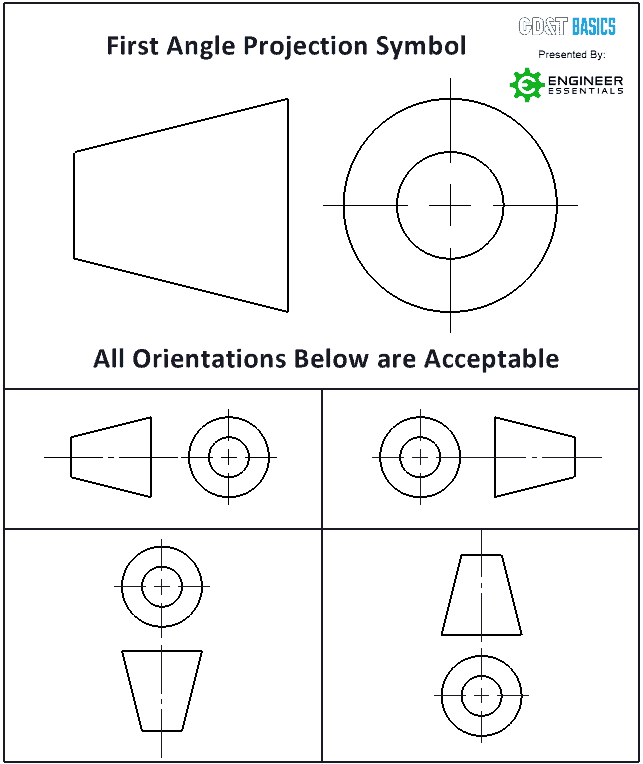 RemarksLEFT VIEW is projected on the RIGHT of FRONT VIEW.
RIGHT VIEW is projected on the LEFT of FRONT VIEW.
TOP VIEW is projected on the BOTTOM of FRONT VIEW.
Another example:
3. HOMEWORK
Homework Worksheet HW3.2.1: Orthographic Views
Use HB pencils to draw on this worksheet HW3.2.1 (<= open and print)
Tips:
The followings are show in perspective.
You may click the following TINKERCAD icons to copy and view them in parallel projections.