3.4 Diodes and LEDs
A. Learning Objectives
- Use ArduinoBlocks.com to program a Wemos D1 board;
- Understand the working principles of LED and RGB LED;
- Make a mini-project using Wemos D1 board, LED and RGB LED.
B. Notes
B1. Diodes
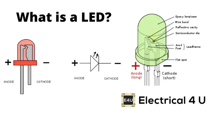
- In a diode, there are two leads: anode (正極) and cathode (負極).
- LED (light emitting diode) (發光二極管) is an example of diode.
- A diode allows current to flow in only one direction, not both.
- A diode can be a conductor (導電體) or insulator (絕緣體), so it is a semiconductor (半導體). Silicon (矽) is an example of semiconductor. P-type silicon and N-type silicon form a PN junction to make a diode.
- As a conductor (In forward bias): anode lead <--> +ve / cathode lead <--> -ve
- As an insulator (In reverse bias): anode lead <--> -ve / cathode lead <--> +ve
- Potential difference across the depletion region in the PN junction is about 0.7V.
- A diode can act as an insulator up to a maximum reverse voltage (反向電壓). Exceeding this voltage limit, it will conduct.
- Diode can be used in a rectifier (整流器) to convert AC (交流電) to DC (直流電) .
- Diode can be tested by a multimeter. It can measure the minimum voltage to turn on the diode and the current start to flow.
Siimulation : Forward and reverse bias | JavaLab
- In a diode, there are two leads: anode (正極) and cathode (負極).
B2. LED (Light-emitting Diode)
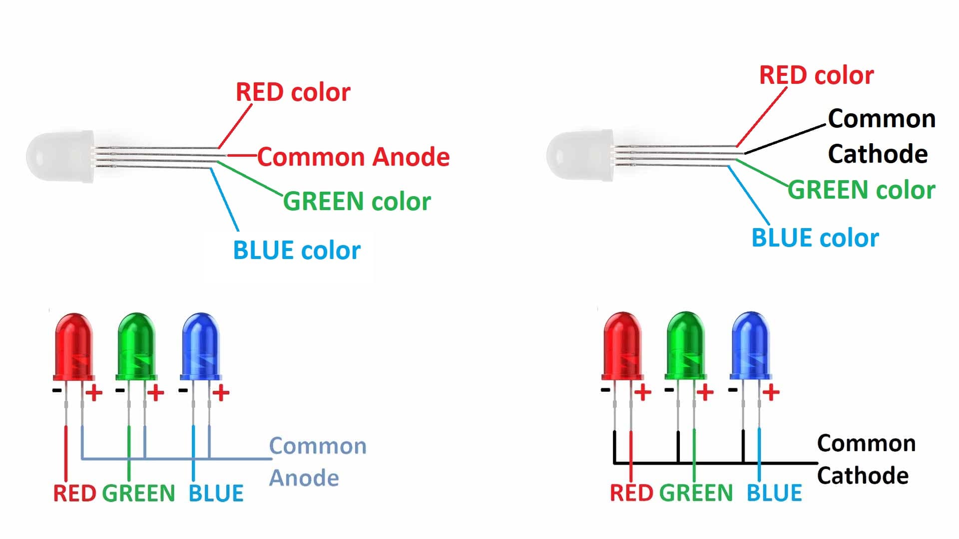
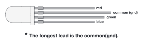
RGB LED
C. Coursework
CW: Traffic Light (10 marks)
Traffic Lights Pattern (Google Sheet)
The pattern sequence of the traffic lights for vehicles:
- Red -> Red & Yellow -> Green -> Yellow -> Red
The pattern sequence of the traffic lights for pedestrians:
- Red -> Green -> Green (Flashing) -> Red
1. Hardware Connection
The whole circuit will be completed on a breadboard. A bread board is a rectangular board which is having lots of HOLES to place electronic components in it.

Each column of breadboard are linked while power lines are linked horizontally.

Be careful of the breaks, the holes between breaks are not linked together.

We will be using 3 LEDs ( Red, Yellow, Green) to simulate the traffic light for vehicles.
There are two leads on the LED, the longer lead is the anthode (+) (connected to higher voltage) while the shorter lead is the cathode (-) (connecrted to lower voltage). In this task, the longer lead of each LED will be connected to an output pin of an Arduino board by a DuPont wire, and the shorter lead of each LED will be connected in series of a resistor to ground (0V).

A resistor should be connected in series of the LED, to limit the current through the LED and to prevent that it burns.
Hardware connection (Vehicle Light)
LED Wemos D1 R32 board Red (Long Lead) IO25 Yellow (Long Lead) IO17 Green (Long Lead) IO16 (-) power bus (with black or blue line) GND (0 V) The LED negative lead (shorter) of each LED is connected to a 100-220 ohm resistor. Another end of each resistor is connected to (-) power bus.
Hardware connection (Pedestrian Light)
RGB LED Wemos D1 R32 board Red pin IO12 Green pin IO13 Usually, we need to use 3 resistors for each R, G, or B pins. However, to save time, we use one 100-220 ohm resistor connecting across the common cathode and GND.
Please refer to the following tinkercad circuit.
https://www.tinkercad.com/things/4pNk9R6Gm9Y
2. Programming in Arduinoblocks (www.arduinoblocks.com)
Project code for S3T2: (See your coursework list)
To light up a LED , we need to use "Write Digital Pin".
- ON: output HIGH voltage (3.3V DC for Wemos D1 / Wesmos D1 R32)
- OFF: output LOW voltage (0V DC)
Reference: Traffic Lights Pattern (Google Sheet)

D. Enrichment
CW: Full Wave Rectification

Make this Full Wave Rectifier in Tinkercad